- 您现在的位置:买卖IC网 > Sheet目录100 > NHD-10032AZ-FSPG-YBW (Newhaven Display Intl)LCD MOD GRAPH 100X32 GRN TRANSFL
[4]?
?
?
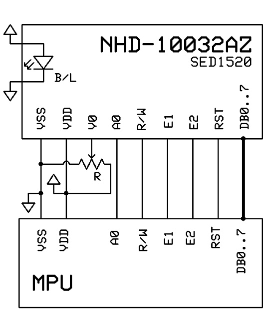
Pin?Description?and?Wiring?Diagram?
Pin?No.?
Symbol?
External?
Connection?
Function?Description
1?
VSS?
Power?Supply?
Ground
2?
VDD?
Power?Supply?
Power?supply?for?logic?(+5.0V)
3?
V0?
Adj?Power?Supply?
Power?supply?for?contrast?(approx.?‐0.5V)
4?
A0?
MPU?
Register?select?signal.?A0=0:?Command,??A0=1:?Data?
5?
R/W?
MPU?
Read/Write?select?signal,?R/W=1:?Read??R/W:?=0:?Write?
6?
E1?
MPU?
Operation?enable?signal.??Falling?edge?triggered,?SEG?(1~60)?
7?
E2?
MPU?
Operation?enable?signal.??Falling?edge?triggered,?SEG?(61~120)?
8?
RST?
MPU?
Active
low
Reset
9‐12?
DB0‐DB3?
MPU?
Four?low?order?bi‐directional?three‐state?data?bus?lines.??These?four?are?
not?used?during?4‐bit?operation.?
13‐16?
DB4‐DB7?
MPU?
Four?high?order?bi‐directional?three‐state?data?bus?lines.??
17?
LED+?
Power?Supply?
Power
supply?for?LED?Backlight?(+5.0V
via?on‐board?resistor)??
18??
LED‐?
Power?Supply?
Ground?for
Backlight
?
Recommended?LCD?connector:?18pos,?1.0mm?pitch?FFC?Connector,?Molex?p/n:?52271‐1879?or?equivalent??
Backlight?connector:?on?LCD?Connector?????Mates?with:??‐?
?
?

发布紧急采购,3分钟左右您将得到回复。
相关PDF资料
NHD-10032AZ-FSY-GBW
LCD MOD GRAPH 100X32 Y/G TRANSFL
NHD-12032BZ-FSW-GBW
LCD MOD GRAPH 120X32 WHT TRANSFL
NHD-12032BZ-FSY-YBW
LCD MOD GRAPH 120X32 Y/G TRANSFL
NHD-12232AZ-FL-YBW
LCD MOD GRAPH 122X32 Y/G TRANSFL
NHD-12232AZ-FSW-GBW
LCD MOD GRAPH 122X32 WH TRANSFL
NHD-12232DZ-FSPG-GBW
LCD MOD GRAPH 122X32 GRN TRANSFL
NHD-12232DZ-FSW-GBW
LCD MOD GRAPH 122X32 WH TRANSFL
NHD-12232DZ-FSY-GBW
LCD MOD GRAPH 122X32 Y/G TRANSFL
相关代理商/技术参数
NHD-10032AZ-FSY-GBW
功能描述:LCD 图形显示模块和配件 100 x 32 STN-GRAY 65.0 x 28.4 RoHS:否 制造商:ELECTRONIC ASSEMBLY 产品: 分辨率:128 x 64 流体类型:FSTN Positive 接口: 背光: 背景色:White 工作温度范围:- 20 C to + 70 C 封装:Bulk
NHD-12032B1Z-FSW-GBW
功能描述:LCD 图形显示模块和配件 STN-Gray Transfl 68.1 x 32.9 RoHS:否 制造商:ELECTRONIC ASSEMBLY 产品: 分辨率:128 x 64 流体类型:FSTN Positive 接口: 背光: 背景色:White 工作温度范围:- 20 C to + 70 C 封装:Bulk
NHD-12032BZ-FSW-GBW
功能描述:LCD 图形显示模块和配件 120 x 32 STN-GRAY 68.1 x 32.9 RoHS:否 制造商:ELECTRONIC ASSEMBLY 产品: 分辨率:128 x 64 流体类型:FSTN Positive 接口: 背光: 背景色:White 工作温度范围:- 20 C to + 70 C 封装:Bulk
NHD-12032BZ-FSY-YBW
功能描述:LCD 图形显示模块和配件 120 x 32 STN-Y/G 68.1 x 32.9 RoHS:否 制造商:ELECTRONIC ASSEMBLY 产品: 分辨率:128 x 64 流体类型:FSTN Positive 接口: 背光: 背景色:White 工作温度范围:- 20 C to + 70 C 封装:Bulk
NHD-12232AZ-FL-YBW
功能描述:LCD 图形显示模块和配件 122 x 32 STN-Y/G 84.0 x 44.0 RoHS:否 制造商:ELECTRONIC ASSEMBLY 产品: 分辨率:128 x 64 流体类型:FSTN Positive 接口: 背光: 背景色:White 工作温度范围:- 20 C to + 70 C 封装:Bulk
NHD-12232AZ-FSW-GBW
功能描述:LCD 图形显示模块和配件 STN-Gray Transfl 84.0 x 44.0 RoHS:否 制造商:ELECTRONIC ASSEMBLY 产品: 分辨率:128 x 64 流体类型:FSTN Positive 接口: 背光: 背景色:White 工作温度范围:- 20 C to + 70 C 封装:Bulk
NHD-12232DZ-FSPG-GBW
功能描述:LCD 图形显示模块和配件 STN-Gray Transfl 65.8 x 27.2 RoHS:否 制造商:ELECTRONIC ASSEMBLY 产品: 分辨率:128 x 64 流体类型:FSTN Positive 接口: 背光: 背景色:White 工作温度范围:- 20 C to + 70 C 封装:Bulk
NHD-12232DZ-FSPG-YBW
功能描述:LCD 图形显示模块和配件 STN-Y/G Transfl 65.8 x 27.2 RoHS:否 制造商:ELECTRONIC ASSEMBLY 产品: 分辨率:128 x 64 流体类型:FSTN Positive 接口: 背光: 背景色:White 工作温度范围:- 20 C to + 70 C 封装:Bulk
